Showing posts with label ARDUINO PROJECTS. Show all posts

Tuesday, 7 November 2017

Obstacle Avoiding Robot using Arduino

Robotics is an interesting and fast growing field. Being a branch of engineering, the applications of robotics are increasing with the advancement of technology.
The concept of Mobile Robot is fast evolving and the number of mobile robots and their complexities are increasing with different applications.
There are many types of mobile robot navigation techniques like path planning, self – localization and map interpreting. An Obstacle Avoiding Robot is a type of autonomous mobile robot that avoids collision with unexpected obstacles.
In this project, an Obstacle Avoiding Robot is designed. It is an Arduino based robot that uses Ultrasonic range finder sensors to avoid collisions.

Circuit Diagram

Arduino Alarm Clock


In this project, we designed an Arduino based Real Time Clock with alarm. A Real Time Clock or RTC is a battery powered clock that measures time even when there is no external power or the microcontroller is reprogrammed.
An RTC displays clock and calendar with all timekeeping functions. The battery, which is connected to the RTC is a separate one and is not related or connected to the main power supply.

Portable Ultrasonic Range Meter

Sound is a phenomena that is a result of vibration of materials. Sound is characterized as a mechanical wave that carries mechanical energy.
For the transmission of this energy between transmitter and receiver, presence of a medium is necessary. The medium can be solids, liquids or gases.

Sunday, 5 November 2017

Arduino LED Matrix


An LED matrix is a two dimensional array of LEDs that can be used to display symbols, characters or even images. Based on the orientation of the LEDs in the matrix, there can be two types of LED matrices.They are Common Row Anode and Common Row Cathode.
LED matrix modules are one of the commonly used display devices and are used in major applications like electronic display panels and notification systems.
In this project, an Arduino Uno board is integrated with an 8 X 8 LED matrix to display information (even scrolling information and images can be displayed).

Circuit Diagram

Rotary Encoder With Arduino


A Rotary Encoder is an electromechanical device that converts angular movement of the shaft to analog or digital code.
Rotary Encoders can be found in radio equipment like amateur radio or hand held, where non-stop or continuous 3600 rotation is required for tuning to right frequency.
In this project, the working of Rotary Encoder is explained with the help of Arduino. The following sections are dived into introduction to rotary encoders, circuit and working.

Circuit Diagram


Frequency Counter Using Arduino

Frequency Counter, as the name indicates, is an electronic device or component, which is used to measure the frequency of a signal. In case of a repetitive electronic signal, a frequency counter measures the number of pulses in that signal.
We generally use an oscilloscope to depict the signal, calculate the time period of the signal and finally convert it to calculate the frequency of the signal. But, oscilloscopes are very expensive and everyone cannot afford it.
Hence, a simple Digital Frequency Counter can be built which might come in handy to measure the frequency of a clock signal, for example.
In this project, an Arduino based Digital Frequency Counter is designed to measure the frequency of an incoming signal.

Circuit Diagram

Friday, 3 November 2017

Arduino Traffic Light Controller

The use of personal vehicles is very common now a days and a result, the number of vehicles on the roads are exponentially increasing. Roads without any supervision or guidance can lead in to traffic congestions and accidents.
Traffic Lights or Traffic Signals are signalling devices that are used to control the flow of traffic. Generally, they are positioned at junctions, intersections, ‘X’ roads, pedestrian crossings etc. and alternate the priority of who has to wait and who has to go.
The traffic lights will provide instructions to the users (drivers and pedestrians) by displaying lights of standard color. The three colors used in traffic lights are Red, Yellow and Green.
The system must be used to control the traffic lights for smooth and safe movement of traffic. These control systems consists of electro mechanical controllers with clockwork mechanisms or modern solid state computerised systems with easy setup and maintenance.
In this project, an Arduino based Traffic Light Controller system is designed. It is a simple implementation of traffic lights system but can be extended to a real time system with programmable timings, pedestrian lighting etc.

Circuit Diagram

Build a Simple Arduino Calculator

A Calculator is a device that is used to perform simple arithmetic operations to complex mathematical calculations. The rise of calculators can be seen from devices like Abacus to credit card sized complex electronic solid state devices in the modern day usage.
Apart from small calculators, which can be used to perform simple arithmetic calculations, calculators also come in complex scientific outlook that can perform various mathematical and statistical operations like trigonometry, algebra, calculus, etc. But such complex scientific calculators can be very costly.
In this project, we will design a simple arithmetic calculator using Arduino UNO, a 16 x 2 LCD display and 4 x 4 Matrix Keypad.

Circuit Diagram

Arduino Mail Notifier

Physical Mail or Post is a method of transporting documents, packages, cards, parcels and letters. This service is usually done by a postal service system. Mail is usually delivered by mail man post man to our homes. We get important documents like bills, invitations, bank statements etc. in mail.
If we don’t check our mail box regularly, we might miss the deadlines for payment of bills etc. It is a tedious job to regularly check for mail as mail boxes are often placed outside the house or in some cases, a common place at the end of the street.
Hence, in this project, a simple but efficient mail notifier system is designed using Arduino and few other components. This system notifies the user whenever there is a mail and hence avoiding the need to check for mail frequently.
The project is based on Arduino, RF Module (RF Transmitter and Receiver) and a light sensor (Photo resistor or LDR).

Circuit Diagram

Since the project is based on RF Modules, the circuit is divided in to transmitter and receiver.
The following image shows the circuit diagram of the Transmitter or Sender part of the project.

Arduino Home Automation Using RF

Home automation is one of in demand concepts in today’s world. Hobbyists do simple automation systems with the components readily available. If we are more concerned about the reliability and performance of the system, then we can go for the expensive Home Automation Consoles.
Home automation reduces the physical efforts and integrates the control for any number of appliances in to a single control unit. Hence, a simple home automation system is a remote control of different electrical appliances i.e. turning them on or off with the help of a remote.
There are many ways to implement this remote control system. With the extensive use of smart phones and tablets, Bluetooth may be the best option to implement the home automation. And one is implemented here in Bluetooth based Home Automation using Arduino.  The other methods of remote controlled home automation system are ZigBee, Wi-Fi, Radio Frequency (RF Module), GSM etc.
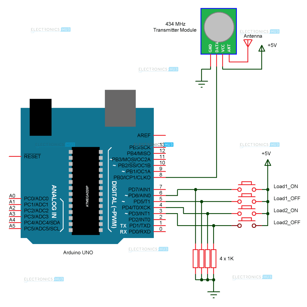
In this project, a simple but efficient home automation system using RF Module (Transmitter – Receiver pair) is designed. The system is designed with Arduino (ATmega 328) as the main processing unit.

Circuit Diagram

The circuit diagram is divided in to the transmitter section and receiver section for easy understanding. The transmitter section of the project is shown on the following image.

Thursday, 2 November 2017

Touch Dimmer Switch Circuit using Arduino

A Touch Dimmer Switch Circuit is a simple project, where the dimmer action is achieved with the help of a Touch Sensor. While a regular switch is used to simply turn ON or OFF a light, a Dimmer (or Dimmer Switch) will allow us to control the brightness of the light. Without a Dimmer Switch, the light bulbs tend to glow at full brightness consuming maximum power. If full brightness is not required, then Dimmer Switches can be used and save some energy. With the help of a Dimmer Switch, we can vary the brightness from fully off to fully on.
Different light bulbs need different dimmer switches and there are different types of Dimmer Switches available in the market. Some of the commonly found Dimmer Switches are Slider type and rotary type.
In this project, we have designed a Touch Dimmer Switch using Arduino. The Touch Dimmer Switch Circuit is implemented using a Touch Sensor. The circuit design, components and working of the project is explained in the following sections.


Arduino Based Color Detector

A Color Sensor, as the name suggests, is a device that senses or detects colors. A color sensor will use an external means of emitting light (like an array of white LEDs) and then analyse the reflected light from the object in order to determine its color.
Color sensors will give an accurate color of the object. There are a wide range of applications of color sensors like sorting objects by color, quality control systems, printer color enhancement etc.
In this project, we have designed a simple Arduino Color Sensor application, which has an ability to detect different colors. We have used TCS3200 color sensors for this purpose. Introduction to color sensor, circuit diagram and working of the Arduino Color Sensor project are explained below.

Circuit Diagram


Use 5v Relay Arduino

Arduino is a microcontroller based prototyping board that runs on small DC power. A Relay is a device that helps microcontrollers (or microcontroller based boards) like Arduino to switch on or off different household appliances like motors, lights, water heaters, television and fans etc.
Today, Arduino is being used for a wide range of applications like controlling LEDs, monitoring temperature, logging data and turning on motors etc. Another important task that can be accomplished by the Arduino is controlling a 5V Relay to operate high voltage AC appliances and devices.
Arduino family of microcontrollers, like UNO, Nano and Mega etc. can be programmed to control a simple 5V relay i.e. switch it on or off on the event of pushing a button, reading the value of temperature from a thermistor or just by setting up a predefined timer.


Arduino based Wireless Doorbell

Traditional Doorbells are wired devices and are usually fixed at one place. They are becoming obsolete because of these reasons and are gradually being replace by advanced Wireless Doorbell Devices. With a wireless doorbell, the position of the switch and the bell is not fixed.
We can place it anywhere we want and also the installation is pretty simple. The setup of wireless doorbell doesn’t require any internal wiring. Also, if the wired doorbell is not fixed while construction, we need to make holes for wiring and installation.
In this project, we have designed an Arduino based Wireless Doorbell using simple hardware. The project is implemented using RF Module for wireless communication and also an Arduino UNO board to analyze the data.


Saturday, 28 October 2017

Arduino Controlled Power Outlet

A power outlet allows electrical equipment and appliances to get connected to AC power. Arduino can be used to control this power outlet in order to turn the electrical equipment or appliance in to a smart device. Normally, we plug in different appliances or electrical devices in to the wall socket and turn them ON or OFF with the help of associated switches on the wall.
In this project, we have used Arduino to control a Power Outlet so that it can be controlled with the help of a sensor or remote switch. We have designed a Power Outlet box with one plug and a switch that is connected to a relay module, which is controlled by the Arduino. For triggering the relay, we have used an LDR light sensor.
Alternatively, the Power Outlet can be made to work with Bluetooth, over the internet with Wi-Fi Module (ESP8266) or any other type of sensor.


Arduino Servo Motor

As mentioned in our Arduino based DC Motor control project, a DC Motor is one of the most commonly used electric motor in electronics, robotics, toys etc. It generally consists of only two wires for electrical connection. When these wires are properly connected and given electrical supply (like a battery), the motor starts rotating. A technique called Pulse Width Modulation (PWM) allows us to control the speed of rotation of the motor.
The story of Servo Motor is entirely different from that of a DC Motor. A Servo Motor is a type of actuator that provides high precision control of linear or angular position. A typical servo motors consists of four things (or parts): a DC Motor (or AC Motor), a gear unit, a position and speed sensing device and a control unit.
Servo Motors are used in applications where very high precision motion is required like assembly robots, computer numeric controls etc.

Circuit Diagram